Tips for Building Smooth Live Tracking
How did we manage to build accurate tracking and smooth animations in our app? Here are your answers.
By Divya Vikash
By Divya Vikash
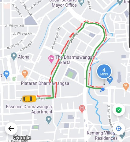
It’s a nice Monday morning and you just ordered a GoRide (one of Gojek’s transport products) to go to your office. Voila!! You got a driver. That was fast. You can see your driver’s location on the map, and the estimated time they would take to come to you.
But hang on… It seems like the map is a bit messed up.
The driver location on the map goes back and forth at unreal speed, and even flies over buildings. Starring in an action movie is not exactly how you want to start your week. 😮
While our driver-partners sure are superman in their own unique way, they certainly can’t drive over buildings. This is clearly not how your driver is actually driving on the road. But then why is the map showing all this?
Well, there are multiple factors that can lead to a bad experience like that. Some within our control, some not so much (as of now). We decided to go back to the drawing board and figure out the issues that are in our control and fix them for good. And that is how we built a world-class (arguably 😬) live-tracking experience.

But what is live-tracking, you would ask?
Live tracking is a complete map experience. It doesn’t involve anything other than what you see on maps after you get a driver.
So, what do you see on maps?
- Driver's location depicted by a green marker.
- The routes.
- The change in driver marker as the driver moves closer to your pickup/your destination.
- The change in route as the driver moves.
And that’s it. That’s all live-tracking is.
But that sounds quite simple. Right? Use some routing APIs and plot the markers and routes.
Well, yes, it sounded easy to us when we first heard about it too. The real experience threw us a few curveballs. Let’s go through how we create a live-tracking experience.
Input
Let’s look at the input data that we need to create a live-tracking animation:
Driver Location and Routes
Our driver apps have an in-built mechanism to upload driver location to our backend at regular intervals. This is how we are able to find a driver close to your location when you order one of our services. The primary input to live-tracking is this driver location.
In our driver app, we get this location using Android’s FusedLocationProvider API which automatically uses the best location provider(GPS, Wifi, etc). The driver location is ingested into our backend system via a continuous stream. Routes are generated by our internal routing engine and provided to the customer app.
Input Source
As you would have guessed, this data is provided via API calls initiated by the our Super App to the routing engine.
Making the API call just once won’t be sufficient. Right? The app needs to be informed every time the driver’s location has changed. So, the customer app polls this API every few seconds to get this data.
Now, we have a continuous stream of data flowing to our app which has all the information that we need to show the vehicle animation on the road.
Terminology
Before moving forward, we should get acquainted with a few terminologies that we would use quite frequently in this post.
- Route: The entire list of latitude-longitudes between the driver location to the pickup/destination location.
- Segment: A segment is the smallest unit of a route. It is a straight line from one position in the routes list to the very next position in the routes list.
A route of length n has n-1 segments. Confused? Yeah, let’s take an example.
A Route looks like this:
[{-62441198, 106.8032959},
{-6.2440766, 106.80328},
{-6.2439977, 106.8033275},
{-6.2434893, 106.8029214},
{-6.2433926, 106.8030539},
{-6.2436018, 106.803222}]
There are 5 Segments in this route.
Segment 1: {-6.2441198, 106.8032959,-6.2440766, 106.80328}Segment 2: {-6.2440766, 106.80328,-6.2439977, 106.8033275}Segment 3: {-6.2439977, 106.8033275,-6.2434893, 106.8029214}Segment 4: {-6.2434893, 106.8029214,-6.2433926, 106.8030539}Segment 5: {-6.2433926, 106.8030539,-6.2436018, 106.8032224}
The initial setup
When the user lands on the live tracking screen, the app immediately makes a call to our internal API to get the driver location and route. Once we get this data, we plot it on the map using the standard GoogleMap methods. googleMap.addMarker(), googleMap.addPolyline() etc.
Sometimes, we don’t have the routing information available immediately, so we just show the driver marker. We also store this data locally in an in-memory cache as we would need it later to do some comparisons.
So, the customer is able to see the markers and routes on the map now. So far so good.
The subsequent updates
As I mentioned earlier, we need to change the position of driver marker and route as the driver moves. The customer app makes a call to the same internal API every few seconds. After the first response, we don’t move any markers or routes on the map until the next response succeeds.
In the next response, we again get the same data points i.e the route and driver location but with different values, of course, if the driver has moved. The next set of data that we get can have the following characteristics:
- Route and driver location don’t change
- Route changes
- Route doesn’t change BUT driver location does
Let’s discuss these cases one by one.
1: Route and driver location don’t change
If nothing has changed, we don’t need to do anything. Probably our driver partner is stuck in traffic. 😞
2: Route changes
This can happen either when:
- The app was not showing any route to the user before i.e the first response didn’t have the route.
- The app was showing a route that is different from the newly received route. This usually happens in cases where the driver starts following a different route from the one they were following before. This can also happen due to road closures or simply because our driver-partner initially followed a wrong route by mistake 😅.
In either of these cases, we simply ignore the old driver marker and routes which were shown and plot the new marker and routes.
3: Route doesn’t change BUT driver location does
The app was showing the same route to the user before i.e the old response had the same route as the new response. This means that the driver is following the original route that we determined.
In this case, we need to animate the driver marker on the map from the old location to the new location along the same route. This is the most common scenario, which can again be broken down further into multiple scenarios (yeah, I’m all about breaking things down 🤐).
3.1: Does the new location lie on the route?
To animate the driver marker from it’s current position to the new location, we first need to know whether the new location lies on the route or not.
Yeah, we can’t be sure that the driver location that we have received would always lie on the route/road because of various GPS inaccuracy issues.
We iterate through every segment in the route to find the segment which has the new location. For every segment, we use the Geometry/PolyUtil library to determine whether the driver location lies on that route.
We also specify a tolerance of a few meters to account for GPS inaccuracy. So, if the newly received location is within a radius of X meters near a segment, this method will return true.
Android
boolean isLocationOnPath(LatLng point,List<LatLng> polyline,boolean geodesic, double tolerance)
iOS
BOOL GMSGeometryIsLocationOnPathTolerance(CLLocationCoordinate2D point,GMSPath * path,BOOL geodesic,CLLocationDistance tolerance)
If the location doesn’t lie on any of the segments in the route, we are sad and so, we don’t animate anything. But if it does, we go forward with the next step which is….
3.2: Vehicle projection on route
When we receive a new location, the start location is simply the position that the driver marker is already at. No logic required there to calculate that.
The end location should simply be the new location that we received. Well, in an ideal world, it should be but we live so far away from an ideal world 😞.
As we mentioned earlier, the raw driver location that we get from the driver app via GPS/other providers mostly doesn’t lie on the road. So, we have to find a projection of the driver location on the road/route.
If you have been reading carefully, you might wonder why we can’t just use the isLocationOnPath() method above 🤔.
Well, if you had been reading more carefully, you might have noticed that this method returns a boolean explaining whether the location is on/near the route or not 🤦♂. It doesn’t return the projected location. (Ohh..if someone from Maps Utils stumbled upon this by chance, please add that method, good sir).
So, we had to revise some maths. Yeah, folks, learn your maths well. You never know when a situation like this might arise 🤷♂.
“Find the projection of point (x,y) on the line y = mx + c”. Does that ring a bell? Drawing a perpendicular line towards the segment and calculating the location of where the line and route intersect can give us the projected location. Right?
Well, the above approach works for 2-D systems but earth is not a 2-D space. We need a way to project the spherical surface of the earth onto a rectangle 2-D space. There are several ways to do that. All of them have certain drawbacks. We might lose information like direction or the shape of landmasses/countries or the area information.
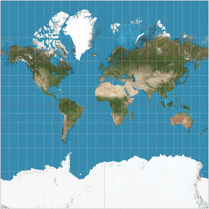
Mercator Projection
Mercator projection is one of the available methods to project the spherical map of earth onto a rectangle to make usable maps. Most of the mapping tools used for navigation use this projection.
The key feature of Mercator projection is that it retains the direction information. That means if point A is 30deg east from north of point B on the globe, it will be in the same direction on its Mercator projection. Or say there is a turn of 90deg in some lane, it will be 90deg on Mercator projection as well. That is the reason it works really well for navigation purposes.
How to use a Mercator projection?
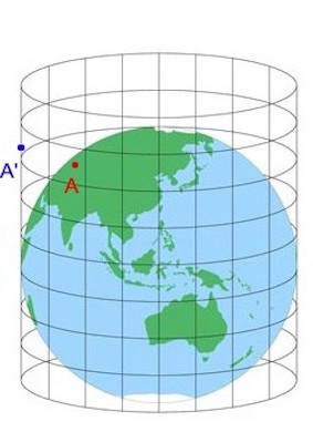
- Every point on the earth is projected on a cylinder exactly like point A which has point A’ on the cylinder.
- Once all the required points/routes are projected on this cylinder. It is unrolled, and we obtain a rectangle like the one shown above.
- All the planar geometry can be applied with a very little margin of error on this 2D projected map.
- After processing all the points/routes they can be converted back to latitude and longitude on the globe.
So, now we have the projected driver location on the route which we will fondly call snapped point going forward.
3.3: End-to-End animation
The new driver location that we receive can be present in any segment. It may be that it is in the same segment or it may be that it is on the next segment or on the next one or it may be that it is on the last segment.
But for linear animation, we need a start point and an end point. The start point is the current position of the driver marker. We already got the snapped endpoint in the earlier section. But we can’t just animate from start to end at once as that would seem like the car is flying and ignoring U-turns, routes, etc. So, how do we prevent it from flying?
What do you do when you can’t fly to a place? You follow the road. Right? That’s what we have to do as well. Make the driver marker follow the route/road. We need to animate along each segment in the route until we reach the segment which has the driver position that we received.
There are again two cases here 😜:
3.3.1: The new driver location is on the same segment
In this case, we can directly animate from the current position of driver marker to the driver location that we received since this is just a straight line animation.
A segment is always a straight line. We will discuss more on how to do the animation b/w 2 points in a later section.
3.3.2: The new driver location is on a different segment
In this case, we need to animate to that segment along the route. We have to animate along each of the segments in between to reach the final segment.
For animation along the first segment, we set the endpoint of the animation to the beginning of the next segment in the route. We animate to the end of the first segment.
The next segment may also not have the driver location that we received. After a driver has traversed the first segment, we move the end location of the animation to the end of the next segment, and so on and so forth till we reach the last segment. Confusing, ya? Let’s see an example.
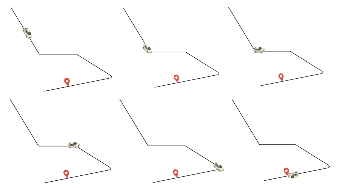
The car icon(A) represents the location in the segment where the driver marker currently is. The red pin(X) represents the new snapped location received.
In the 1st animation, we move the driver marker from A to the end of the first segment (B).
In the 2nd animation, the driver marker is moved through the entire length of the 2nd segment.
And so on and so forth till we reach the segment which has the newly received snapped location (X).
Animation in a segment
We now know how the overall animation would look like. But we also need to configure how the smallest unit of the animation i.e animation in a segment should happen.
Start point and End point: For case #1 above, the animation in a segment will happen just once. For case #2 above, this animation in a segment will happen multiple times. Start and endpoints will be determined before beginning each of the animations.
Bearing b/w these two points: Bearing can be calculated using another one of Geometry/Maps Utils method.
SphericalUtil.computeHeading(startPosition, endPosition)
Duration of animation: Calculating duration is a bit tricky. And the duration is the most important thing in any animation. Sometimes the difference b/w a smooth and a choppy animation is caused by the duration. It was very important that we got it right. So, let’s take a break and see how to calculate the duration.
What is Duration?
It’s the amount of time for which the animation should happen. But you already know that. Going back to middle school maths (yeah, that far), how do you calculate time? Time is nothing but distance divided by speed. Correct? Calculating straight line distance b/w the two points we want to animate through is pretty easy.
SphericalUtil.computeDistanceBetween(startLocation, endLocation)
Cool, cool. But what about speed? How should we calculate speed?
Speed calculation
FusedLocationProvider API in the driver app does provide the speed of the vehicle but it’s highly unreliable. So, we have to employ some tricks to calculate the speed.
Speed is distance divided by time. Distance again!! Seems like we are running in circles 😵. Not exactly. Here the distance is not the straight line distance b/w the two points that we have to animate through.
This is the total distance along the route from the segment that the old driver location is currently located at, to the segment where the new driver location is. Yeah, that statement is a bit confusing. So, let’s take an example.
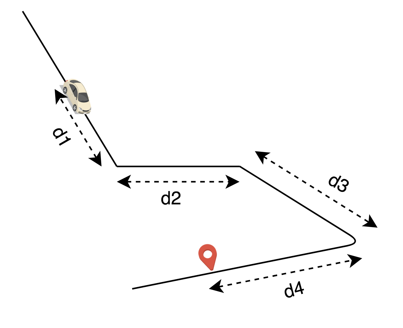
The car icon(A) represents the location in the segment where the driver marker currently is. The red pin(X) represents the new snapped location received. To calculate the distance, we do the obvious:
Total distance = d1 + d2 + d3 + d4
Now, we have the distance. We need the time interval.
The FusedLocationProvider API in the driver app does provide us the timestamp at which a location was updated. And this information is passed to our backend and subsequently to the customer app.
We calculate the time difference b/w the old driver location and the new driver location using their timestamps. Wait, how do we know the old driver location? As we had mentioned earlier, we cache the last available driver location and route in an in-memory cache.
Total route distance divided by time and now we have the speed for the entire duration. Linear distance divided by this speed and now we have the durationfor a single animation in a segment. Cool, so let’s get back to the point where we broke off 😅.
Update the animation
With all the above information, we start the animation. But wait? Aren’t we missing something? We did start an animation b/w two points but how will our animator know how to animate?
Animation is just a bunch of frame updates that happen every fast. How do we update the marker position, the starting point of the route, the rotation in each and every frame of the animation? Well, the mobile/web framework allows us to do something every time the frame is updated.
But what is this something that we should do?
1. Update marker’s position
For markers, we need to update their position. Once we have the position, we can simply update the marker position using the marker.setPosition(). To find the position during each frame of the animation, we need the percentage of animation that has elapsed.
We can get the percentage from the Animation framework. Using this percentage and the start and end position, we calculate the intermediate position/s like this:
SphericalUtil.interpolate(startPosition, endPosition, fraction)
2. Update Routes
Routes need to be aligned with the marker’s movement. So, we update the routes as well using the values above and updating the polyline points of that route using the polyline.setPoints().
And that’s a wrap. The result that we get is a very smooth, measured movement of the vehicle along the road.
There are a few more tips/tricks that we employ to ensure that there are no abrupt changes in the animation.
But that’s for next time. 😃
What’s next?
We still need to go a long way to meet the standards that we have set for ourselves. Currently, this new experience is only rolled out to GoRide, GoCar, and GoBluebird. We are working on bringing the same experience to other services like GoFood, GoSend, and GoShop. Stay tuned for more!

Want stories like this one beamed straight to your inbox? Sign up for our newsletter!
Thanks to Koushik Krishna, Abhay Sood, Anup Cowkur, Sooraj Rajmohan, and Kshitij Choudhary.